Part 1. Mirror and Glass Materials
1) Show a sequence of six images of scene `CBspheres.dae` rendered with `max_ray_depth` set to 0, 1, 2, 3, 4, 5, and 100. The other settings should be at least 64 samples per pixel and 4 samples per light. 2) Point out the new multibounce effects that appear in each image, and 3) explain how these bounce numbers relate to the particular effects that appear. Make sure to include all screenshots.
|
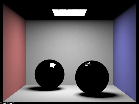
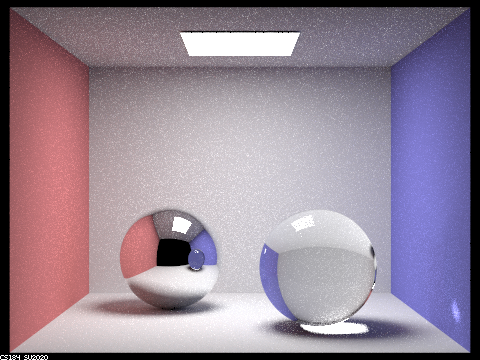
When rendering with 0 max_ray_depth, the render result only includes the direct illumination from the light source, as expected. This is because with a max_ray_depth value of 0, only light rays from the camera that hits a light source directly have a non-zero return value through zero bounce illumination. At least one bounce illumination is immediately halted upon entering the funtion, so everything else is black.
|
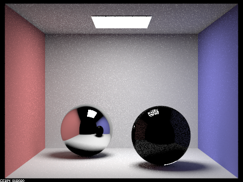
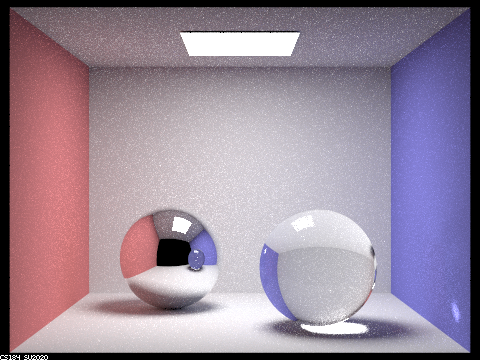
With 1 maximum ray depth, the reflections from the walls as well as the spheres begin being rendered. Since there is only one reflection allowed after hitting the balls, only direct illumination hitting the spheres would be illustrated. This results in only the light source being reflectd on the balls. Also notice that the ball on the right has a darker reflection than the one on the left: this is because the right ball has the glass bsdf in which only $ 1/R $ of the light rays hitting its surface are sampled as reflected, where $R$ is Schlick's reflection coefficient. The rest of the light hitting the right sphere are refracted and not rendered (since they do not hit a light source after refracting).
|
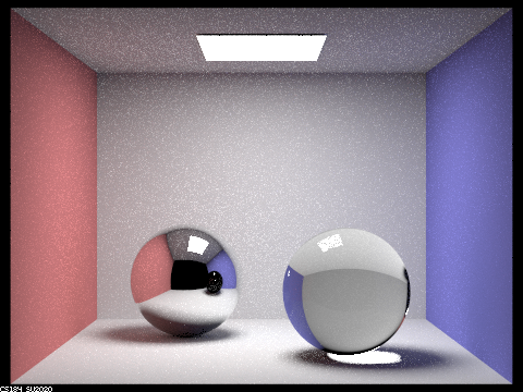
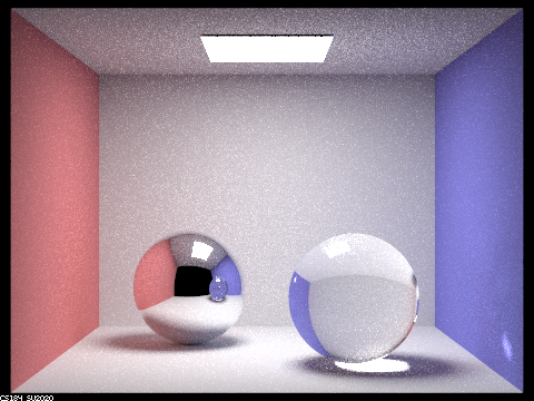
With 2 maximum ray depth, the reflections from the ceiling are also rendered. They were not rendered in the last picture because at least 1 bounce is required after hitting the ceiling for a ray that reaches a light source to be rendered. Similarly, the reflections that requires 1 bounce after hitting the spheres to hit a light source are rendered, resulting in the reflection on both balls. Notice that the reflections on the right spheres are still much darker because of the same reason where only a fraction of the rays hitting it are reflected. Lastly, the refracted rays are still unrendered: the just reached the surface from inside of the sphere and still require one more bounce to reach a light source, so the right sphere is still largely black.
|
With 3 maximum ray depth, the refracted rays are finally beginning to reach the light source, resulting in the right sphere's refractions of the objects behind it being rendered. However, Note how the reflection of the right sphere on the left sphere still only has reflections and no refractions. This is because the rays that go through those paths still need one more bounce (due to being reflected instead of directly hitting the right sphere) to reach the light source, and thus are still unrendered.
|
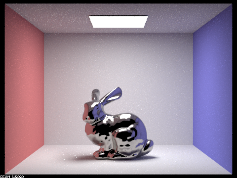
With 4 maximum ray depth, the reflected image of the right sphere is finally rendered. As previously explained, those rays requires at least 4 bounces to be rendered and thus are only just rendered. Along with this, a bright spot on the blue wall is rendered. The additional brightness come from the reflection from the bright spot under the sphere, also requiring 4 bounces to be rendered: the blue wall, the floor, refract into the sphere, and out of the sphere.
|
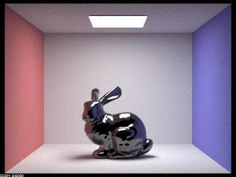
With 5 maximum ray depth, there are few outstanding improvements from the 4-maximum ray depth render. One notable feature is that there are a few bright pixels in the middle of the reflection of the right sphere in the left sphere, this is the reflection of the bright spot on the blue wall that we talked about in the last step.
|
With 100 maximum ray depth, few further notable improvements can be found. One last notable thing to mention in this part is that the image becomes brighter (degree of which exponentialy decays) with every additional ray depth, this is because more ray bounces would enable more global illuminations to be rendered. Also note that the reflected and refracted images are always 1 and 2 steps behind, respectively, because the ray passing through those parts of the image need to take additional steps before reaching a light source.
Part 2. Microfacet Material
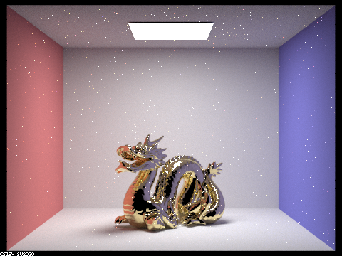
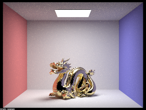
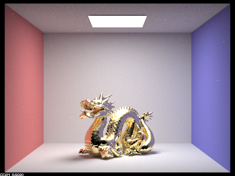
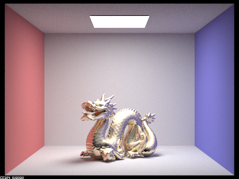
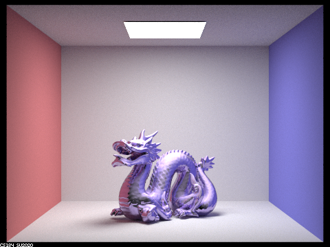
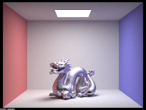
Show a screenshot sequence of 4 images of scene `CBdragon_microfacet_au.dae` rendered with $\alpha$ set to 0.005, 0.05, 0.25 and 0.5. The other settings should be at least 128 samples per pixel and 1 samples per light. The number of bounces should be at least 5. Describe the differences between different images. Note that, to change the $\alpha$, just open the .dae file and search for `microfacet`.
|
|
|

|
As can be easily observed, the $\alpha$ value alters the roughness of the microfacet material. The higher $\alpha$ is, the closer the texture is to lambertian texture; while lower $\alpha$ makes the texture more similar to mirror texture. A higher value of $\alpha$ models a higher frequency of microfacets on the surface and thus a rougher surface.
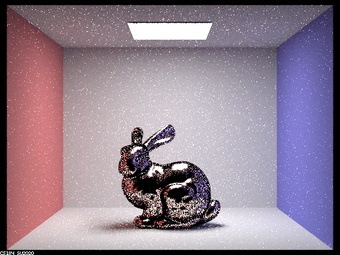
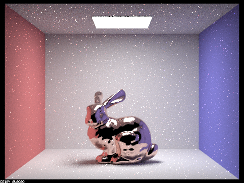
Show two images of scene `CBbunny_microfacet_cu.dae` rendered using cosine hemisphere sampling (default) and your importance sampling. The sampling rate should be fixed at 64 samples per pixel and 1 samples per light. The number of bounces should be at least 5. Briefly discuss their difference.
|
|
The scene is rendered with 64 sampels per pixel, 1 sample per light, and 5 maximum ray depth. Although both finishes in an acceptable ammount of time, the render result from hemisphere sampling is significantly noisier. This is because hemisphere sampling samples uniformly, which is inefficient as most of the light has little to no influence to the final render result, while importance sampling samples light in directions more likely to contribute to the scene, resulting in a higher render quality with the same number of samples.
Show at least one image with some other conductor material, replacing `eta` and `k`. Note that you should look up values for real data rather than modifying them arbitrarily. Tell us what kind of material your parameters correspond to.
|
|
|
|
|
The above is a demonstration of various materials we attempted. Below is a reference table for their refraction coefficient ($\eta$) and extinction coefficient ($k$):
| $\lambda$ = 614nm (Red) | $\lambda$ = 549nm (Green) | $\lambda$ = 466nm (Blue) | |
|---|---|---|---|
| Bismuth |
$\eta = 2.2260$ $k = 3.0795$ |
$\eta = 2.0273$ $k = 2.8541$ |
$\eta = 1.7531$ $k = 2.5252$ |
| Carbon |
$\eta = 2.4124$ $k = 0.0000$ |
$\eta = 2.4228$ $k = 0.0000$ |
$\eta = 2.4346$ $k = 0.0000$ |
| Brass |
$\eta = 0.33660$ $k = 3.0824$ |
$\eta = 0.52630$ $k = 2.4064$ |
$\eta = 0.94580$ $k = 2.0158$ |
| AuAl2 |
$\eta = 1.3345$ $k = 2.2091$ |
$\eta = 1.8252$ $k = 1.9416$ |
$\eta = 0.98574$ $k = 3.2882$ |
| PtAl2 |
$\eta = 1.9691$ $k = 3.2435$ |
$\eta = 1.9169$ $k = 2.9323$ |
$\eta = 2.2762$ $k = 3.9519$ |